EC11 incremental rotary encoders are user-interface controls for electronic devices. They’re particularly useful for quickly adjusting settings through a range of possible values, or for scrolling through lists or menus. They’re also relatively inexpensive, and pretty easy to find. The way these devices work is rather interesting, and somewhat surprising if you’re unfamiliar with it. In the remainder of this post, for brevity, I’ll simply refer to them as EC11’s.
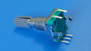
EC11’s look similar to potentiometers, but they’re very different devices. A potentiometer turns smoothly through a limited range of motion, but an EC11 turns in discrete steps, and its range of rotation is unlimited. A potentiometer is a variable resistor divider, but an EC11 has nothing to do with resistance. Instead, when it rotates, it produces signals that indicate the direction of rotation. EC11’s can also function as push buttons.
As a side note, I’m not sure why they’re called “EC11” encoders. My web search on this topic has turned up nothing useful. I’ve also seen references to EC12 and EC16 encoders, that presumably differ in some important way. There are likely other types as well. The best I’ve been able to come up with is that “EC” stands for “EnCoder”, and the 11 means 11 mm, for (I guess) the shaft length. However, apparently, EC12’s and EC16’s don’t have the push button feature that EC11’s have, so I’m not convinced that’s the whole story. If you know more about this, please let me know.
Electrical Interface
An EC11 has five pins. There is no standard pin labeling, at least not that I could find, but it’s common for the pins to be labeled A, B, C, D, and E. The pinout diagram below is one possible labeling, and is the one I’ll use for this post. Note, however, that some documents have the A and B pin labels swapped.
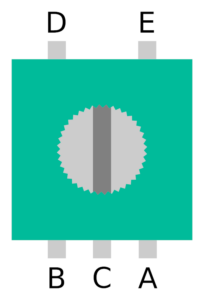
Pins D and E are used for the button functionality. They are normally disconnected from each other, but are shorted together when the shaft is pressed like a button. This is relatively straightforward, and behaves just like almost any other push button. The other signals are a little more surprising. Pins A, B, and C provide information about rotations, but they’re not simply “clockwise,” “counterclockwise,” and “ground” pins, as I initially expected.
C serves as a common pin, and A and B work together to indicate whether the shaft is being turned, and in which direction. They do this by connecting and disconnecting from C using something called quadrature encoding. When the EC11 is not being turned, A, B, and C are all disconnected from each other. As the shaft is turned clockwise through one step, the following connections and disconnections happen in sequence:
- A is connected to C,
- B is connected to C,
- A is disconnected from C,
- B is disconnected from C.
For counter-clockwise rotations, the roles of A and B are reversed. Note that only one of the two signals changes at any one time. This encoding enables a simple mechanical design for the device, and also eliminates ambiguous transition states that could arise if both signals changed at nearly, but not exactly, the same time.
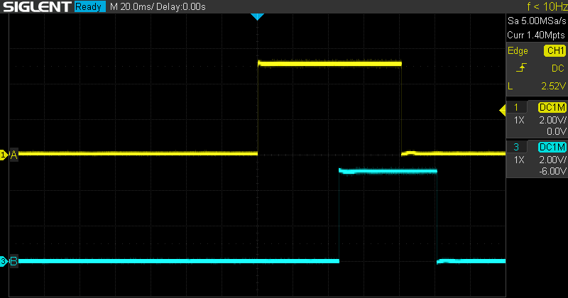
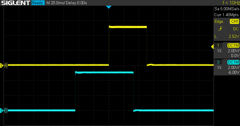
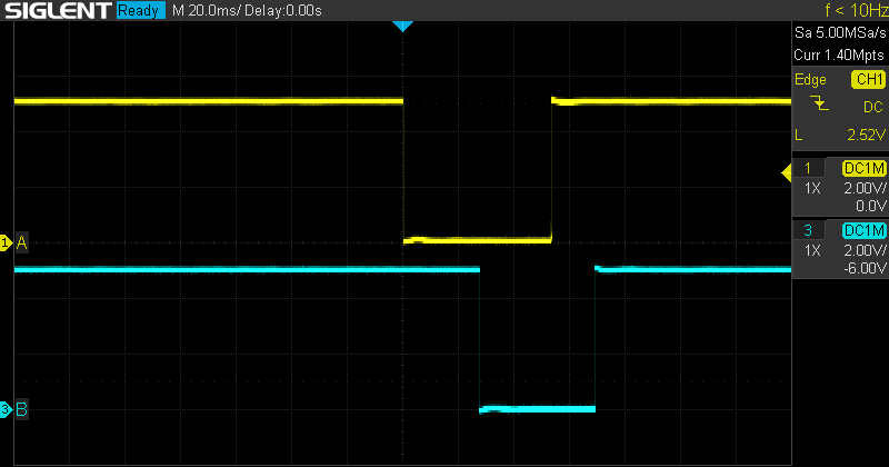
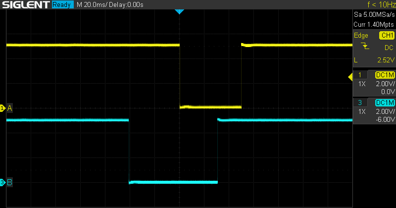
To illustrate these signals a little better, I connected an EC11 to an oscilloscope and took some captures. (An oscilloscope shows a graph of voltage on the vertical axis vs. time on the horizontal axis.) In all of these images, A is the yellow trace, and B is the blue trace. For the first two images, C was connected to VCC (+5V), and A and B were each pulled down to GND (0V) with 10kΩ pull-down resistors. This means that A and B are normally low, but are high while connected to C. The first image shows clockwise rotation, and the second image shows counter-clockwise rotation.
For the next two images, C was connected to GND, and A and B were each pulled up to VCC with 10kΩ pull-up resistors. This means that A and B are normally high, but are low while connected to C. As before, the first image shows clockwise rotation, and the second image shows counter-clockwise rotation.
The choice of connection method may depend on various factors in the larger circuit, but often it will work just fine either way, and the choice is made arbitrarily or by personal preference of the circuit designer.
Mechanism
Before we dig into this section, I should point out that I haven’t actually taken one of these devices apart, so what follows about the specifics of their construction is speculation and educated guesses on my part. The precise nature and arrangement of the internal parts may differ from what I describe. However, I believe the basic principles are correct.
My understanding is that inside the body of an EC11 are two wipers, or conductive contacts—one connected to pin A and one to pin B. The shaft is attached to a rotating plate with a pattern of conductive pads that can make electrical connections to the wipers. These pads are connected to pin C. It’s a bit hard to explain with words, so here’s a diagram:
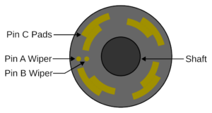
This diagram is very approximate. For instance, actual EC11’s have many more than four positions. The ones I’m using have twenty. However, it should communicate the basic idea. As the shaft and plate rotate, but the wipers stay stationary, one wiper will connect to a pad, then the other wiper will, and then the first wiper will disconnect, then the second will, just as described above. The mechanism also includes detents that cause the shaft and plate to snap into place with the wipers between pads.
As I said, some of the details above may not be exactly correct. It’s possible that the wipers move with the shaft over stationary pads. It’s possible that the pads are not on a plate perpendicular to the shaft, but actually placed on the surface of the shaft itself, with the wipers oriented sideways. It’s possible all these methods, and others, could be used by different models of encoders. However, I’m reasonably confident that the general principles outlined above are correct. I welcome feedback and/or corrections from anyone who knows more about this than I do.
Contact Bounce
Things like switches, buttons, and rotary encoders are all subject to a phenomenon known as contact bounce. This means that the physical conductors inside the mechanism can actually bounce off of each other and introduce spurious connections and disconnections before finally settling down to the correct state. This can make it appear as though, for example, a button was pressed several times when the user only meant to press it once.
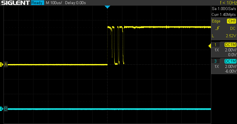
To demonstrate contact bounce with the EC11, I took another oscilloscope capture, this time significantly zoomed in on the time (horizontal) axis. In the previous captures, the oscilloscope was set to 20 ms per division (i.e. background grid cell). To be able to show the bouncing, I set the oscilloscope to 100 μs, or 0.1 ms, per division. There is some inherent randomness to the bouncing. Sometimes the contacts don’t bounce at all. Sometimes they bounce a great deal. I ended up turning the EC11 a few times to get a good example of bouncing to capture. The following image was taken with the EC11 connected with positive polarity, and the shaft was rotated clockwise.
There are several ways to deal with contact bounce, including both hardware and software solutions, with varying levels of complexity. It might be worth going into this topic in more detail in a future post. However, one simple software solution is to keep track of the previously read value of the input pin, and introduce a delay between reads. The software can then react when there’s a difference between the previous value and the current value. If the delay is sufficiently short, the user won’t notice it, and if the delay is sufficiently long, the bouncing will have stopped by the time the pin is read again. In practice, I’ve found that delays of a few milliseconds work pretty well.
Arduino Sketch
I’ve put together a simple circuit and Arduino sketch to demonstrate how to use these devices. Feel free to use or adapt this code in your own projects. We’ll first take a look at the hardware setup, then we’ll discuss the code.
This example uses an Arduino Uno R3, but it should work with almost any Arduino. Similarly, while this example (somewhat arbitrarily) uses Arduino pins 2, 3, and 4 to connect to the EC11, any free GPIO pins should do. The EC11 is connected with positive polarity. (Changing the hardware connections and sketch code to use the EC11 with negative polarity is relatively straightforward, and is left as an exercise for the reader.)
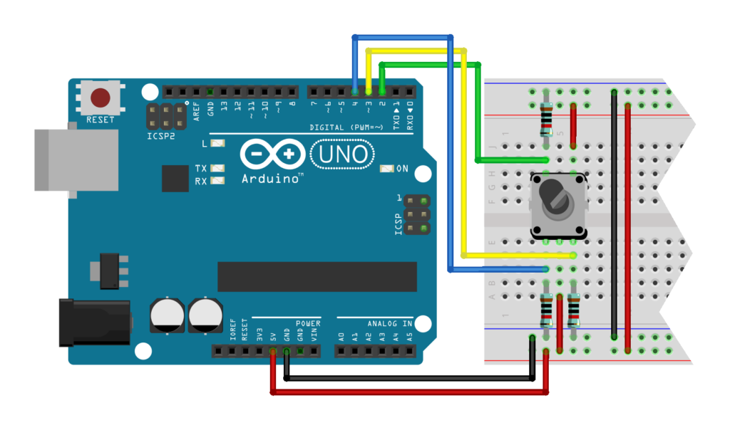
Connect the Arduino’s 5V pin to the positive breadboard rails and connect the Arduino’s GND to the negative breadboard rails. Connect EC11 pins C and E to the positive rails as well. Connect EC11 pins A, B, and D to the negative breadboard rails through 10kΩ resistors. (Since these are pull-down resistors, the resistor values themselves don’t matter too much, as long as they’re large-ish.) Connect EC11 pin A to Arduino pin 3, EC11 pin B to Arduino pin 4, and EC11 pin D to Arduino pin 2.
Now that the circuit is hooked up, we can move on to the code. The following code uses a simple polling loop with a basic software debouncing scheme, and simply prints messages over the serial connection when the EC11 is rotated or pressed. It should be straightforward to adapt this code to do other things on these events instead.
To read the rotation state, we first check to see if pin A is going from low to high. This rising edge occurs every time the EC11 is rotated. The direction is then determined by looking at the B pin at the moment of A‘s rising edge. In a clockwise rotation, A goes high before B does, so while A is going high, B will still be low. In a counter-clockwise rotation, B goes high before A, so while A is going high, B will already be high. If this isn’t clear, it might help to take another look at the oscilloscope captures above.
We only need to check B when we’ve already determined there’s a rising edge on A, so the code below omits that check in other cases. Also note that we don’t need to debounce B, because bouncing happens right after a state change, and we only read B well before or after its state changes.
The button press events are handled slightly differently from the rotation events. We check for both rising and falling edges on the button input. A rising edge corresponds to the button being pressed, and a falling edge corresponds to the button being released. It’s sometimes useful to track both types of button events, so they’re included in the example.
//
// ec11_example.ino
//
// Example Arduino sketch to demonstrate reading an EC11 rotary encoder
//

// Pin definitions
#define EC11_PIN_A 3
#define EC11_PIN_B 4
#define EC11_PIN_D 2

// Number of milliseconds to wait between pin reads, for software debouncing
#define DEBOUNCE_DELAY_MILLIS 3

// Global variables to hold the previous state of the EC11 pins, initialized
// to LOW. We don't need to track the previous state of B to debounce it
// because we don't read it near an edge, and any bouncing should already
// have stopped by the time we do read it.
int prevA = LOW;
int prevD = LOW;

// Runs once at beginning of sketch
void setup()
{
  // Set pins to input
  pinMode(EC11_PIN_A, INPUT);
  pinMode(EC11_PIN_B, INPUT);
  pinMode(EC11_PIN_D, INPUT);

  // Initialize serial connection
  Serial.begin(9600);
}

// Runs continually in a loop after setup is complete
void loop()
{
  // Local variables to hold the current state of the pins
  int currentA;
  int currentB;
  int currentD;

  // Wait a bit to allow any contact bounce to settle
  delay(DEBOUNCE_DELAY_MILLIS);

  // Process rotation pins
  currentA = digitalRead(EC11_PIN_A);
  if ((prevA == LOW) && (currentA == HIGH))
  {
    // There's a rising edge on A, so the EC11 is being rotated. The state
    // of B at the rising edge of A indicates the direction. If B is low,
    // then A went high first, and the rotation is clockwise. If B is high,
    // then B went high first, and the rotation is counter-clockwise.
    currentB = digitalRead(EC11_PIN_B);

    if (currentB == LOW)
    {
      Serial.println("Clockwise");
    }
    else
    {
      Serial.println("Counter-clockwise");
    }
  }

  // Process button pin
  currentD = digitalRead(EC11_PIN_D);
  if ((prevD == LOW) && (currentD == HIGH))
  {
    Serial.println("Pressed");
  }
  else if ((prevD == HIGH) && (currentD == LOW))
  {
    Serial.println("Released");
  }

  // update previous state globals
  prevA = currentA;
  prevD = currentD;
}
After building this circuit and compiling and uploading the sketch to the Arduino, open the serial monitor and set it to 9600 baud. Then, turn and press the EC11. You should see output similar to the following in the serial monitor:
Clockwise
Counter-clockwise
Pressed
Released
Pressed
Clockwise
Counter-clockwise
Released
Summary
So, that’s about as much as I can say about the EC11 rotary encoder. It’s a cool little device, and can be used to build pretty nice user interfaces for hobbyist projects using Arduino’s, or Raspberry Pi’s, or any other microcontroller. Feel free to reach out if you have any questions/comments/corrections about anything in this post.
Leave a Reply